


WORM GEAR EFFICIENCY.
Page 26
Page 27
If you've noticed an error in this article please click here to report it so we can fix it.
With Special Reference to David Brown and Sons' New F.J. Type, and the Results of Recent Tests Conducted by the National Physical Laboratory and Now Published for the First Time.
UNTIL COMPARATIVELY recent years, the utilization of worm gear for the final drive on commercial-motor vehicles did not become very popular, and was, in fact, used only by one or two enterprising manufacturers, amongst whom were Dennis Bros., Ltd. of GuildforcL The adoption by the London Genera). Omnibus Co., Ltd., of the worm gear gave it a fillip, and its advantages, particularly as regards silence, efficiency and reliability, were thus continuously demonstrated before the eyes of both the public and the manufacturers'. Until that time the worm gear was looked upon as being a somewhat inefficient method of-obtaining silence, and a way of obtaining a reduction greater than. 5 to I without necessitating the use of double-reduction rear axles.
Worm gears have, of course, been used for many years in connection with other classes of machinery., but they were used chiefly as a means of transmitting motion where the power losses did not materially. affect the question. • Their improvement really cormmenced with thoa increase in the use of high-speed electric' motors in which worm gears were found of great use in obtaining the considerable reductions required with this type of drive ; the design, and machining of gears then became more exact. The first difficulties experienced with worm gears, as applied to commercial-motor vehicles, were due to incorrect tooth form and machining, non-standardization, unsuitable mounting, and unsuitable lubrication, and at one time it was considered that ordinary gear grease or engine oil would do just as well in the rear axle casing on a worm-gear-driven vehicle as in that of a vehicle fitted with bevel gear . as the final drive. It was ,not,however, until tests were con ducted by the Daimler Co. on therDaimler-Lanchester worm gear testing machine that the efficiency .of. modern worm gearing began to be thoroughly understood. Previously the loss which -occurred in a rightangle transmission Was reckoned at -about 10 per cent., but this loss with the-latest type of worm gear, which -is that :manufactured by David Brown and Sons (littdderifield), Ltd. and known as the F.J. type', has been reduced to between three and four per cent, at normal speeds, and this With worm gears entirely machine finished by the standard David Brown process.; in fact, the..exe.ellent efficiency of 96.7 per cent. was recently recorded withina20 minutes
of a worm gear commencing to run. .
Some of Our readers may perhaps think that we are over emphasizing the importance of decreasing the frictional losses in the final transmission. We would point out to users that every decrease in these losses mean-a. -decrease in -petrol consumption and maintenance; frictional losses -mean wear;. not only between the worm and the -wheel, but throughout the whole mechanism. Efficiency isnot obtained by using a highly' efficient engine and inefficient transmission.
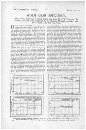
We publish a series of charts showing the efficiencies obtained 'with the Diwid Brown F.J. type worth gear at various speeds and transmitting varying h.p. The Curves are shown as compared with the previous world's records obtained on the Daimler-Lanchester worm gear testing machine. It will be seen that in every case the F.J. typo has efficiencies well above the world's record.
Consideringthat practically all present-day worm ;ears are correctly machined, there can be little doubt that the very high efficiencies obtained are due, in no sm-all measure,. to the special patent form of tooth
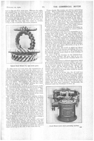
used on the new F.J. worm gear. Whereas the ordinary parallel typeof worm. gear has a straight-sided form of tooth on the linear section, the F.J. gear is made with a special curved contour arrived at by mathematical calculations. We are not concerned in this article With the actual calculations, which are of an exceedingly difficult character ; we are only concerned with the fact that they must he correct, owing to the wonderful efficiencies obtained.
In older forms-of worm gears the transmission of velocity between the worm and the wheel was not uniform, also the load was not evenly distributed over the worm wheel teeth, and the action between the teeth and the gears was mainly sliding. The high rubbing velocity with the ordinary parallel type of worm gear, together with the unsymmetrical lines of contact introduces a concentrated load which tends te produce the worst possible conditions on the leaving side of the worm wheel. This explains why, with the ordinary type of gear, if overloaded, pitting first takes plaae on the leaving side of the wheel.
A description of the methods of manufacture of the type worm gear may be of interest to our readers. The keynote of the system is "generation." The shape of the rotary worm milling cutter is generated, the teeth of the worm wheel are, of eourse, generated, and, yet again, the contour of the threads of the worm are ground by a pure generating process.
The D.B.S. worm milling machine consists of three main castings—the bed, the head and the horizontal table. The head lies at right 'angles to the work table, and the cutter spindle is carried in a cover which enables it to be set at any angle to suit the spiral of the worm being cut. One end of the worm, which is mounted on the horizontal table, is gripped by a collet chuck, while the other end is moanted in a self-centring roller steady. As the table moves lengthwise the worm is rotated by the dividing worm and wheel mounted at the right of the machine ; thus the motions are combined to suit the spiral angle of 'the worm. When the cutter head is moved forward to the correct depth (measured by micrometer) the worm rotates spirally in front of. the cutter' thus milling a thread space for each travel of the table. The worms are made of , a fine quality mild steel ease-hardened after milling, and to remove any dis-. tortion of the worm thread caused by the hardening process the worms are'grourid in a machine, a special feature of which is the manner in which the abrasive wheel is fed up to the side of the warm thread. Worm wheels-, like worms, are cut by a generating process. This is performed bymeans of a hob which resembles a finished worm,' except that it is gashed along its leugthlo provide cutting faces. The worm wheel blank is mounted on a revolving tahlewhich is driven at a speed varying according to the ratio of the gears being cut, whilst the hob travels longitudinally across the face of the wheel. Owing to the spiral of the hob, this travel has to be compensated for by means of 'a differential. The final operation is performed with a patent reamer hob, which ensures a perfect shapemf tooth with a smooth Surface.
Every worm and wheel is tested mast thoroughly by special machines and instruments to ensure perfect tooth form and interchangeability.
It is interesting to note that it is' impossible to introduce hand work on the new type of gear without spoiling the tooth contact. Any hand work or preliminary "bedding in" would upset the scheme or manufacture. In this connection it may be remarked that on previous tests. which were carried out by the National Physical Laboratory a representative of the laboratory witnessed the final stages of manufacture, sealing the gears as they were taken off the machine, and with these same gears efficiencies of up to 97.3 per cent. were obtained. In the latest tests, the result of which are shown by the charts which we are now publishing, the worm gear tested had a ratio of 4.2 to 1, the worm having five threads and the worm wheel 21 teeth working at 6-in, centre distance.
In order to fit the bearings on the Daimler-Lancheater testing machine, the gear had to be constructed of a certain size, but the machine finish was absolutely standard.
The, testing apparatus is a delicate instrument which gives results guaranteed -correct to within 1 per cent, l`t.is designed directly to measure the loss of pewer, or, to be more exact, it measures the ratio of the driving tolque and the driven torque.. If the efficiencies were perfect, i.e.,,100 per cent.; the driving torque multiplied by the gear ratio would be exactly equal to the driven torque. To make the test. 'a severe one, the oil used was artificially heated so as' to maintain a temperature 'of between 50 and and60 degrees Centigrade, whereae.the oil used on the tests for the previous world's record was at a temperature of between 30 and 50 degrees Centigrade. The lower temperature of working is distinctly in favour of the gear, and thus these results are even more conclusive. Incidentally the lubricant used was Duckham's D.E.S. oil.