


Differential Gears Explained and Illustrated.
Page 17
If you've noticed an error in this article please click here to report it so we can fix it.
It is not always necessary to fix the differential on the back axle of-the car, but a differential countershaft is sometimes introduced instead, the ends of which carry sprockets, and the road wheels are driven from these sprockets by
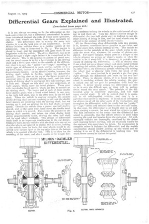
chains. The differential acts in exactly the same way whether it is on the hind axle or the countershaft. In the Milnes-Dahnler vehicles there is a further variety of the differential. This is illustrated in Fig. s. The engine is placed in front, and the crankshaft and gear shaft all run lengthwise with the vehicle. The drive, therefore, has to be turned through a right angle before it is transmitted to the, road wheels. This is the practice in almost all petrol cars, and the usual course is to fix a bevel pinion to the driving shaft and a bevel spur wheel to the outside of the differential; that is to say, the " spider " or " cage," according to which type of differential is used, carries outside of it a big bevel wheel, instead of a chain sprocket as shown in the diagrammatic figures. In the Milnes-Daimler, however, the driving shaft, which is flexible, carries the differential pinions. The big claw at the top of the figure is part of a universal joint in the flexible driving shaft, and this short length of driving shaft is carried on two ball bearings, one at each end. Forged on this shaft are two projections, at right angles, which carry the bevel pinions. These gear with two double bevel sleeves, which are free to revolve on the driving shaft. The larger end of each of these double bevel sleeves gears with a bevel wheel bolted, in one case, to the right half shaft, and, in the other case, to the left half shaft. When the vehicle is moving straight, the pinions on the driving shaft are not revolving at all, and the double bevel sleeves are revolving with the driving shaft, but not turning on it, and are driving the two half shafts at equal speeds. Directly tile vehicle turns a corner, one half shaft is slowed, and, at the same time, itself slows the double bevel sleeve to which it is geared. This makes the pinions on the driving shaft revolve, and drives the other double bevel pinion proportionately faster, driving the other half shaft and its road wheel similarly. This design of differential lends itself to an important modification in the car design. Ordinary horse-drawn vehicles with the fixed axle are set so that the wheels are splayed or dished, that is to say, looking at the vehicle from the back, the road wheels would be observed to be further apart at the top edge than at the bottom which is in contact with the road. This is to allow for the rounding of the roads, and also it results in the weight hay
ing a tendency to keep the wheels on the axle instead of trying to pull them off. With the Milnes-Daimler design of differential, the two half shafts may be inclined to one another instead of being in line, and the road wheels may be splayed in the manner of horse-drawn vehicles.
All the illustrations show differentials with two pinions. It is, however, considered better practice to use three, and in some cases four, pinions instead of two. This makes no difference to the principle of the gear, which works in exactly the same way, whatever the number of pinions employed. For heavy vehicles, where there is a danger of the wheels slipping on greasy or slippery roads, or when the vehicle is on a steep hill, it is necessary to provide some means of locking the differential. It will be obvious that if one wheel got on a slippery place, and spun round without propelling the vehicle, there would be no propelling effort on the other wheel, the differential simply revolving and driving the wheel that is slipping with twice the speed of the "spider." The usual method is to provide a pin that goes right through the differential and locks up the two half shafts. Then, in slippery places, if it is found that one wheel is revolving without the vehicle moving, the gear is locked and the car gets its propulsion from both the wheels. A driver should unlock his differential as soon as he is over the difficult spot, or there will be serious strain round the next corner. The principle of the differential gear is extremely ingenious, and will well repay careful study. It will be noticed that it is essential to all self-propelled vehicles, and that it is a part that must never be neglected. It is not at all infrequent for drivers to oil all the other parts of the mechanism, and to neglect the differential, with the result that the "spider" or " cage" seizes and remains fixed to the two half shafts. In that case, the differential is no longer able to act and, when turning a corner, the near wheel has always to skid. The first intimation to the owner that the differential has seized is, generally, that the vehicle refuses to steer when entering the yard and knocks down the gate-post. All wellmanaged vehicles are thoroughly examined by the driver each morning before starting, and are examined weekly by the engineer who supervises the driver. No examination is complete unless it includes the differential, and the weekly examination should involve jacking up one wheel and revolving it to see if the differential is working free. Too. much stress cannot be laid on this point.