


:ING SYSTEMS
Page 47
Page 46
Page 48
Page 49

If you've noticed an error in this article please click here to report it so we can fix it.
TO impart velocity to a vehicle and to abstract velocity from it, elaborate and ingenious mechanisms are required. It would be an exaggeration to say that as much has been done in developing apparatus for dissipating energy stored in a moving vehicle as in advancing the means for generating the power in the first instance, but the subject of brakes is an extremely large one. Our object here is briefly to review the corn4 monly used methods of braking, discussing their respective merits and outlining some of the principal mechanisms employed.
Braking systems may roughly be classed as nonservo, self-energizing, power-assisted and powerapplied. The first is suitable only for vehicles of moderate weight, the whole shoe-expanding force needing to be created by the driver by muscular effort. In the second, the mechanism within the drum is devised in such a way that the rotational tendency of the shoes is itself employed to contribute to the expanding force. This system is popular as being inexpensive and light in weight, whilst it enables comparatively heavy machines to be brought to rest quickly and without undue muscular exertion.
The Popular Power-assisted Brake.
For vehicles weighing from about 2i tons upwards, power-assisted brakes are widely used. In these, a separate source of energy is applied to the brake shoes in definite proportion to the driver's foot pressure. Finally, there is the power-applied system, in which no effort is exerted by the driver beyond the operation of a light control valve.
The two commonly used sources of energy for the third and fourth systems are vacuum and compressed air, the suction, or pressure, being generated by the vehicle engine or, on trolleybuses, by a separate electric motor. There are various combinations of certain of these main types.
We have made no reference to the regenerativebraking principle, as this is applicable to only one class of vehicle, running in circumstances which render it practicable to employ the energy of momentum to do useful work, instead of being wastefully dissipated, as is at present unavoidable in all other cases. The regenerative-braking system was fully described in our issue dated February 8, 1935.
632 The day has not arrived when an air compressor or other device can be harnessed to the road wheels and utilized at once to slow the vehicle, and to build up a store of power for subsequently speeding it up.
So far, only methods of obtaining braking power have been considered. There remain the means for transmitting it. These in dude systems of rods, shafts and levers. cables and pipe lines. With regard to the last-named, sometimes these serve as direct communication between the air or vacuum valve and the brake cylinders, and sometimes contain fluid columns which transmif the braking force hydraulically.
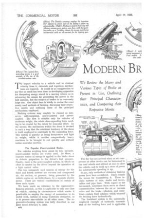
The Lockheed system is the universally employed example of hydraulic transmission of the braking force and is applicable to any of the four main types outlined above. Among its advantages are the perfect compensation automatically afforded and the simplicity of the layout. There are no joints requiring lubrication and subject to wear, whilst the flexible tubular connections permit articulation. The above reference to perfect compensation brings to mind a point of great interest, namely, the apportioning of braking force between the front and rear axles.
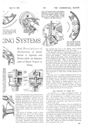
By the act of braking, weight is transferred from the rear to the front wheels. Therefore, it is desirable for front-wheel braking force to be progressively increased, that on the rear wheels remaining constant. A recently introduced mechanical device which merits praise as representing a definite step towards this end is the Bendix Auto Control (illustrated diagrammatically on the next page).
This ingenious device is incorpored in the rod to the rear brakes and allows equal distribution up to a
certain pedal pressure. When this is exceeded, the spring, shown in the sketch, yields, allowing the rollers to be expanded by the wedge, so that the moving unit locks in its fixed guide. Thus no further tension can be imposed upon the rear brake rod, but there is a link gear in the system, between the pedal and the Auto Control, which now comes into active operation, the rear-brake-rod pin acting as the fulcrum point, so that all further pedal pressure is directed to the front wheels.. We forecast that developments on similar lines will make their appearance in other types of brake system in the future.
The plain cam is a simple mechanical means for expanding the shoes, which gives a quick initial movement
• and greater force as the angular movement increases. An involute contour, however, is preferred by some makers. This imparts a constant pressure and, as the angular motion increases as the facings or drum surfaces wear down, it is preferable in that no change of braking pressure for a given camshaft torque takes place during the life of the wearing parts.
Shoe Expansion by Toggle Gear.
An alternative is a toggle arrangement which, in many cases, is attractive from the point of view of deign. An interesting and, we believe, unique application of this system, which was recently described in The Commercial Motor, gives, by the use of two toggles, a parallel shoe movement, thus dispensing with the need for hinge pins.
Constant expanding pressure, such as is afforded by the involute cam, is an advantage of the latest Bendix and Girling brakes. In both, the principle is to pull or thrust a wedge between the heels of the shoes.
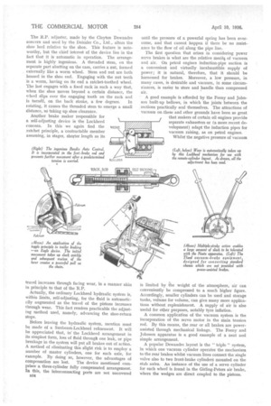
A variety of methods of adjusting brakes is employed. In practically every mechanical system provision is made for altering the angular position of the cam relative to the control. Separation of the shoe ends at the fulcrum points by a wedge is simple and effective and has an advantage that it brings into use portions of the fabric that, during the period preceding adjustment, have been least worn away. The R.P. adjuster, made by the Clayton Dewandre concern and used by the Daimler Co., Ltd., alters the shoe heel relative to the shoe. This feature is noteworthy, but the chief interest of the device lies in the fact that it is automatic in operation. The arrangement is highly ingenious. A threaded stem, on the separate part abutting on the cam, carries a nut, formed externally like a worm wheel. Stem and nut are both housed in the shoe end. Engaging with the nut teeth is a worm, having on its end a ratchet-toothed wheel. The last engages with a fixed rack in such a way that, when the shoe moves beyond a certain distance, the wheel slips over the engaging tooth on the rack and is turned, on the back stroke, a few degrees. In rotating, it causes the threaded stem to emerge a small distance, so taking up shoe clearance.
Another brake maker responsible for a self-adjusting device is the Lockheed concern. In this we again find the ratchet principle, a contractable member assuming, in stages, shorter length as its
travel increases through facing wear, in a manner akin in principle to that of the R.P.
Actually, the ordinary Lockheed hydraulic system is, within limits, self-adjusting, for the fluid is automatically augmented as the travel of the pistons increases through wear. This fact renders practicable the adjusting method used, namely, advancing the shoe-return stops.
Before leaving the hydraulic system, mention must be made of a Sunbeam-Lockheed refinement. It will be appreciated that, in the Lockheed arrangement in its simplest form, loss of fluid through one leak, or pipe breakage in the system will put all brakes out of action. A method of eliminating this slight risk is to employ a number of master cylinders, one for each axle, for example. By doing so, however, the advantages of
compensation are lost. The device mentioned cornprises a three-cylinder fully compensated arrangement. In this, the interconnecting ports are not uncovered until the pressure of a powerful spring has been overcome, and that cannot happen if there be no resistance to the flow of oil along the pipe line.
The first question that arises in considering power servo brakes is what are the relative merit % of vacuum and air. On petrol engines induction-pipe suction is a convenient and virtually inexhaustible supply of power ; it is natural, therefore, that it should be harnessed for brakes. Moreover, a low pressure, in many cases, is desirable and vacuum, in some circumsta.nces, is easier to store and handle than compressed air.
A good example is afforded by the Feeny and Johnson built-up bellows, in which the joints between the sections practically seal themselves. The attractions of vacuum on ;these and other grounds have been so great that makers of certain oil engines provide separate exhausters or (a more recent development) adapt the induction pipes for vacuum raising, as on petrol engines.
Whilst the negative pressure of vacuum is limited by the weight of the atmosphere, air can conveniently be compressed to a much higher figure. Accordingly, smaller cylinders can be used and storage tanks, volume for volume, can give many more applications without replenishment. A supply of air is also useful for other purposes, notably tyre inflation.
A common application of the vacuum system is the incorporation of the servo motor in the main tension rod. By this means, the rear or all brakes are powerassisted through mechanical linkage. The Feeny and Johnson apparatus is a good example of a neat and simple arrangement.
A popular Dewandre layout is the " triple " system, in which one vacuum cylinder operates the mechanism to the rear brakes whilst vacuum lines connect the single valve also to two front-brake cylinder § mounted on the stub axles. An instance of the use of a servo cylinder for each wheel is found in the Girling-Peters air brake, where the wedges are direct coupled to the pistons. Air and vacuum systems are easily adaptable to trailers and articulated vehicles, the Westinghouse being a well-known example of the former. The flexible pipe line solves simply the problem of the universal connection at the king-pin or coupling.
Rapidly gaining popularity is the combination of power With fluid transmission, most of the leading powerbrake makers producing a combined servo motor and Lockheed master-cylinder unit.
A vacuum-servo system specially adapted for
converting vehicles unequipped with powerassisted brakes is the Theed, which enjoys considerable popularity among operators because
of the ease with which it can be installed in a variety of standard chassis, almost without modification of the existing mechanisms.
For heavy vehicles, large articulated outfits and trailers, the power-applied brake, air or vacuum, is extremely successful. It can be controlled by hand or foot and may incorporate a regulating valve, by which the pressure available is adjustable to suit driving conditions, road surface, load, etc. Trailer brakes that are thus operated are easy to use and effective and, ac
cordingIy, the driver is encouraged to negotiate falling gradients in the safest manner, namely, by holding the outfit with the rearmost wheels.
It is undeniable that, for these types of heavy machine, the power brake is almost a necessity, but it is certainly desirable that a mechanical means for application should supplement it. In the early days of trailers, the" second man." screwed down a brake block on the trailer tyres and control at times was hazardous
Operation from the cab was unsatisfactory, largely because of the unavoidable slack in the cable, until the introduction of the Neate brake of the multiple-stroke type. This, operating through a ratchet, wound up the cable on a kind of drum and provided such a satisfactory solution to the problem that it is still widely and successfully employed, despite the advances made by power-braking systems._ A brake, resembling the Neat in some respects, is the Servis, made by Messrs. Henry Boys and Sons, and another ingenious method of combating the slack problem is found in the Eagle device illustrated on the preceding page.